DIY
Tesla Model S Lighted T Installation Instructions

The Tesla Model S Lighted T is a tasteful and unique accessory for any Model S owner who’s looking to add a bit of extra flair.

Image source: Rick Hesel
The Model S Lighted T was developed over a period of about 6 months by Rick Hesel, a Model S P85 owner who began developing modifications for his car before it was even delivered (in May 2013). Over a period of several months a number of betas were developed and tested by a group of six Model S owners. The production version, manufactured in Hong Kong, was developed in collaboration with Oznium Inc, an online retailer specializing in LED accessories.
Rick is developing several other accessories, including a lighted T for the deck lid and a front-rear camera switch, which deploys a Tesla rear camera on the front of the car and enables switching from rear to front views on the touch screen. These accessories will be made available in April 2014.
Tesla Model S Lighted T

Image source: Tesla Motors Club
Installation of the aftermarket Tesla Model S Lighted T can be handled by any savvy do-it-yourself owner or aftermarket shop. Follow these simple step-by-step instructions for a quick and easy install.
UPDATE: EVannex has created an all-ecompasing Lighted T package which contains all necessary components for the installation
Required Parts / Supplies
- Lighted T and Arch (BUY)
- 22 gauge red and black hook-up wire
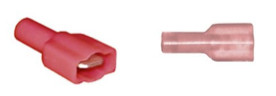
- Male spade connectors
- Female quick disconnect terminals
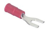
- Fork spade connectors
- Posi-tap wire connector assortment
- Turtle Wax T-529 Label & Sticker Remover
Other parts for Oznium controller installs
Other parts for Oznium install with in-dash monitor option
- 1/8 watt 400ohm resistor and LED
for remotely monitoring status of Lighted T when used with Oznium controller (Optional)
Installation Tools
Installation Steps
Remove Model S Nose Cone
The first step of the process is to remove the Model S nose cone.
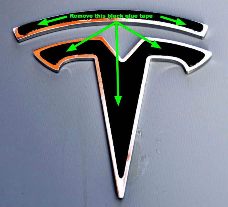
Remove Factory Tesla T and Arch
Slide dental floss behind the emblems and use a back and forth sawing motion until the emblems are fully detached. Use adhesive remover to remove all glue residue from the back of the factory Tesla T and arch.
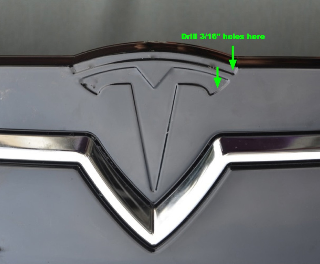
Feed Power and Ground Leads
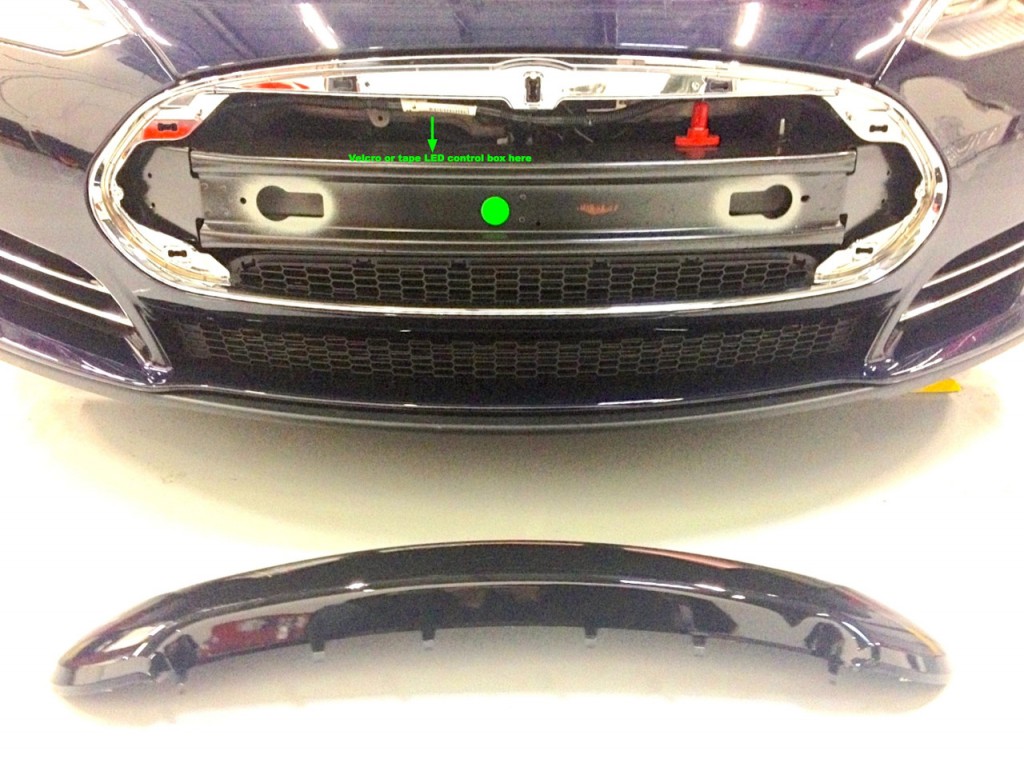
Drill 3/16” hole on top right side of indentation for the T and arch and feed the power and ground leads of the Tesla Model S Lighted T through these holes.
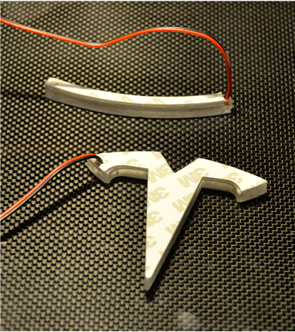
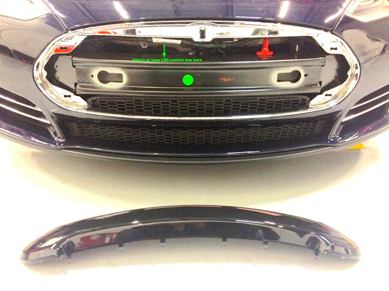
Secure Tesla Model S Lighted T
Remove the 3M adhesive on the back side of the Lighted T and arch. Press the pieces firmly into their respective indentations on the nose cone. Locate the red and black leads from the Lighted T and arch and strip about ¾’ from their ends. Then tightly twist together ends of red leads. Do the same with the black leads.
Crimp a male spade connector on the ends of these black and red leads.
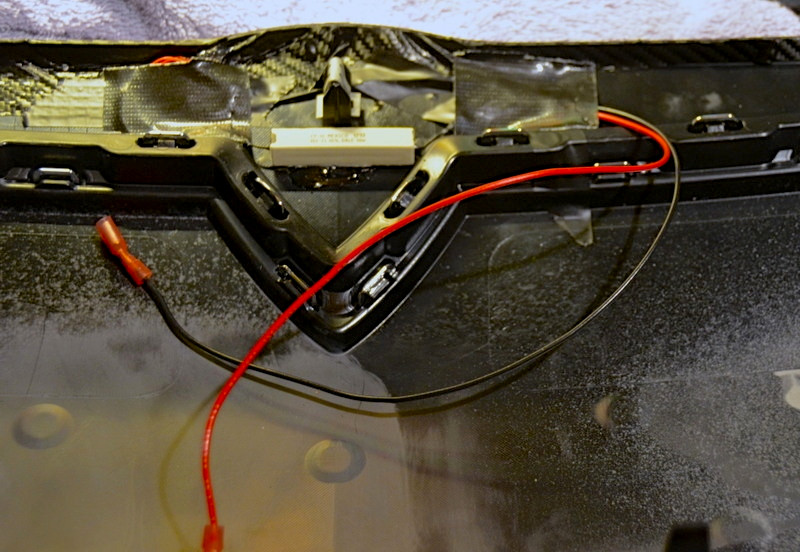
From the back of the nose cone, carefully tape the wires from the T and arch to the back of the nose cone away from the V part of the assembly. Secure the wires (we used duct tape) to a flat surface.
Mount Factory Tesla Emblem onto Lighted T
Remove the 3M adhesive on the front side of the Lighted T and arch. Take the factory chrome Tesla emblems and press them firmly on top of the Lighted T and arch.
Remove Front Trunk “Frunk” Plastic Liners
Remove the driver’s side plastic frunk liner using the Plastic pry tool.

Tesla Lighted T Power On/Off Options
Powering on and off the Tesla Lighted T can be achieved through three types of options – on/off with the headlights, with the daytime running lights (DRL) or through a custom dimmer option.
 Power On/Off with Headlights (Option 1)
- DRL (Option 2)
- Oznium Dimmer Controller (Option 3)
Power On/Off with the Headlights

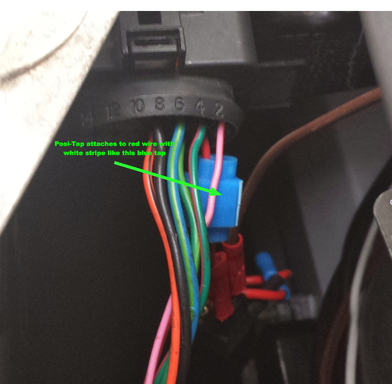
In the exposed area under the liner locate the wire connector plugged in to the back of the headlamp assembly. Locate the red wire with a white stripe. It’s the first wire closest to the nosecone in the lower row. That wire provides 12v power to the headlamps and will be tapped to provide 12v power to the lighted T and arch. Gently pull that wire apart from the surrounding wires.

Take a Posi-tap connector of appropriate size. Following the instructions for the Posi-tap (see video: http://www.youtube.com/watch?v=Yiimgl-Rdmw) screw on the tap side to the red wire with white stripe. Attach a 3 foot piece of the red hook-up wire to the connection end of the Posi-tap then screw it back on to the Posi-tap assembly.
Next run attach a female spade connector to end of the red lead from the Posi-tap. This will connect to the male connector on the lighted T and arch.
To complete the power and ground connection, crimp a female spade connector on the end of a 2’ long piece of black hook up wire and then crimp a fork spade connector large enough to fit on 10mm bolt on the other end.
Loosen one of the several 10mm bolts connected to the aluminum frame under the frunk plastic piece you removed and attach the U spade connector and tighten down the bolt. This grounds the circuit

Place the nose cone near the front of the car just under the crash bar and carefully connect the red female spade connector from the headlight connection to the red male connector on the lighted T and arch. Do the same with the black connection from the ground.
Before snapping the nose cone back into place, turn on the headlights. The Lighted T should light. If not test all of your connections to make sure they are correct and secure.
With testing complete, snap the nosecone back into place on the front of the car, taking care to thread the leads from the T in front of the chrome piece to which the top clip of the nose cone attaches, taking care not to crimp or otherwise stress any of the connections.
Power On/Off with the Daytime Running Lights
Follow the same instructions as powering the lighted T from the headlights, but with one exception – attach the Posi-tap to the orange wire with black stripe in the headlamp wire plug bundle. All other steps are the same as the on/off with headlights procedure.
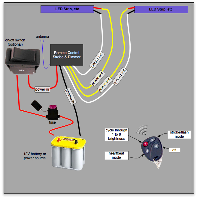
Power on and off with special effects (dimming, strobe, and heartbeat) using the Oznium controller
- Crimp a male spade connector on the ends of the red (12v input) and black (ground) leads on the Oznium receiver box.
- Crimp a female spade connector on the ends of the yellow (12v output) and white (ground) leads of the Oznium receiver box. Only one set pair of the yellow and white wires is needed. The other pair can be clipped off or ignored.
- Using double faced tape or Velcro, attached the Oznium receiver box to the top of the crash bar about a foot left of center.
- Locate the Add-A-Fuse. Crimp a male spade connector to the red lead. The take 4 foot piece of red hook-up wire and crimp a female spade connector on one end and connect it to the Add-A-Fuse male spade connector.
- Place the 5-amp fuse into one of the Tap-A-Fuse slots. Then pry off the cover to Fuse Box #2, locate and remove fuse F47 (the glove box light fuse), insert that fuse into the second Add-A-Fuse slot, then insert the Add-A-Fuse into the empty fuse slot.
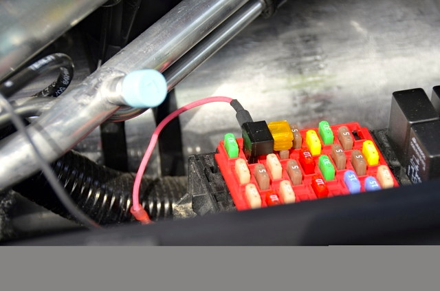
- File a small notch into the Fuse box cover so it will clear the protruding Add-A-Fuse red lead. Replace the fuse box cover with the red lead loosely placed in the frunk opening.
- In the space under the frunk liner, run the red lead from the Tap-A-Fuse to the top of the metal crash bar behind the nose cone and cut it for the proper length to attach to the red lead of the Oznium receiver box.
- Crimp a female spade connector on the cut end of this lead.
- Crimp a female spade connector on the end of a 2’ long piece of black hook up wire.
- Crimp a fork spade connector large enough to fit on 10mm bolt on the other end.
- Loosen one of the several 10mm bolts connected to the aluminum frame under the frunk plastic piece you removed and attach the fork spade connector and tighten down the bolt. This grounds the circuit.
- Connect the red wire female spade connector from the Tap-A-Fuse and the black ground wire female spade connectors to the red and black male spade connectors on the Oznium receiver box.
- Place the nose cone near the front of the car just under the crash bar and connect the female spade connector on the yellow lead from the Oznium receiver box to the male spade connector on the red lead from the lighted T.
- Do the same with the female spade connector from the white lead on the Oznium receiver box and the black wire male spade connector from the T and arch.
- Now take the Oznium controller and press button #1. The T and arch should light up. Successive presses on button #1 should dim the T and arch. Similarly, test buttons #2 (strobe) and #3 (heartbeat) to be sure they are working properly.
- Turn off the T and arch by pressing button#4.
- With testing complete, snap the nosecone into place on the front of the car, taking care to thread the leads from the T in front of the chrome piece to which the top clip of the nose cone attaches, taking care not to crimp or otherwise stress any of the connections.
- If you car has the Tech Package with Homelink you can sync operation of the Oznium remote with Homelink. Do so following the syncing instructions for Homelink on the touchscreen. You’ll need to sync the on function with button #1 on the Oznium remote and the off function with button #4.
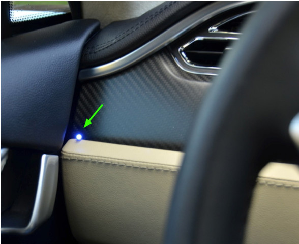
Optional dashboard LED monitor of Oznium 12v dimmer This provides a simple way to monitor the status of the lighted T if it’s controlled by the Oznium 12v dimmer and strobe switch. An LED is wired in parallel with the output of the Ozium controller, a resistor is added to the circuit, and the LED is placed in an inconspicuous place on the dash, as shown in the photo below. Here’s how:
- Cut a about a 6 foot length of the black and red hook up wire (long enough to reach from the Oznium controller output connections (yellow and white), under the diver’s side frunk cover, through the door jam, and into the left side of the dash. Strip off about ¾ insulation from each wire on one side.
- Before crimping spade connectors to the Oznium yellow and white wires (step B.1.b above), twist together the ends of the yellow and red wires, then the white and black wires. Then crimp a female spade connector on each. Make the connection to the lighted T as above, and route the red and black hook up wires along the fender channel. Then run the wire through the narrow opening where the fender meets the door jam. Pull the wire through into the door area.
- Next pull the rubber seal away from the door jam and run the wire under it.
- Using your pry tool, remove the small flap on the side of the dash. Solder a 1/8 watt 400ohm resistor to the red wire then solder the other end to the anode side (long lead) of the LED. Then solder the black wire to the cathode lead (short) of the LED. Insulate all of the wires. Bend the leads of the LED at about a 45 degree angle as close as possible to the LED head, then gently slip the LED into the gap between the vinyl cushion and the fascia of the dash. Stuff all of the excess wire into the side opening then snap the cover back on. The LED will mimic the operation of the lighted T.
Installation Video
Buy
- Tesla Model S Lighted T – $185.00 (BUY)
[box type=”bio”] Note: The Lighted T and Arch does not fit the early Model S Signature versions due to the unique curvature of the nose cone.
Tesla owners have long griped about the wireless phone charger in the Model Y and other vehicles. It often turns smartphones into miniature ovens rather than reliably topping them up.
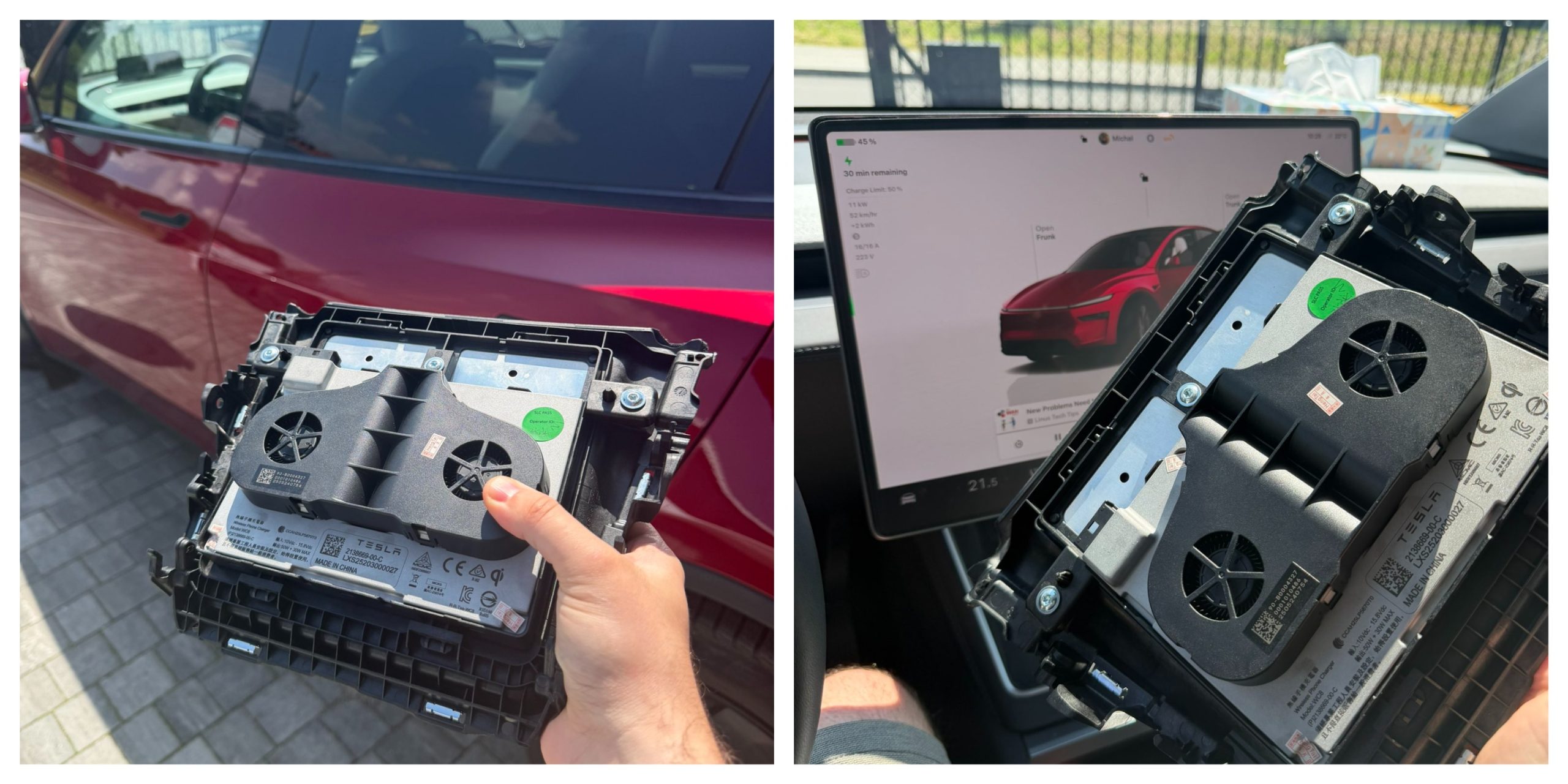
Software engineer and Model Y owner Michał Gapiński tackled this issue head-on with a clever DIY upgrade, swapping the cooled wireless charger pad from the China-made Model YL in for the one that came standard in his vehicle.
There are several key differences between the U.S.-built Model Y’s wireless charging pad and the one that Tesla has been installing in the Model YL. The one installed in U.S.-built vehicles lacks active cooling and relies on basic heat dissipation, leading to rapid temperature buildup during charging. In contrast, the Model YL integrates a small fan for active cooling.
Will it fit? Fingers crossed, I want a first YL charger deployed in the regular juniper pic.twitter.com/wWDqSNFVkW
— Michał Gapiński (@mikegapinski) June 2, 2026
This design maintains lower temperatures even in warm ambient conditions, though it does not support faster Qi2 charging on iPhones. The connector matches exactly, making physical swaps feasible on compatible consoles, but coding is required to enable full functionality.
Owners in the U.S. have complained about the wireless charging pad, with many reporting that overheating is fairly common. Within 20 or 30 minutes of placing a phone on the wireless charging pad, many have reported overheating messages on their phones, which halt charging and essentially turn the pad into a fancy place to rest your phone.
Many owners have opted to simply plug their phones into a charging cord. Tesla has acknowledged the problem by releasing several solutions for owners, including a relatively new feature that allows you to simply turn off the charging and simply act as a holder for your phone while driving.
Gapiński said that he sourced the cooled pad affordably from China, and it cost under $200 for the part.
He removed the existing console charger, swapped in the new unit, confirming a perfect connector fit, and handled the trim differences. Since the parameter isn’t fully secured, he enabled it through custom coding outside official Toolbox.
Connector is identical, she fits, now time to code it. https://t.co/Y9idgDrpCq pic.twitter.com/uwwgq6blg7
— Michał Gapiński (@mikegapinski) June 2, 2026
The fan activates quietly, blending with AC and seat cooling. He reported the installation was effective and the wireless charging pad worked perfectly; it even kept the phone cool as it stayed at just 86 degrees Fahrenheit. Many times, the wireless charging pad will bring the phone’s temperature well above 100 degrees, sometimes even being relatively hot to the touch.
The retrofit worked, no issues. First Model Y with a cooled wireless charger! No QI2/faster charging on the iPhone but it does not boil the phone even when it is 30 degrees outside.
The fan kicks in, it is not audible especially with the air conditioning and seat cooling. The… https://t.co/JOyR8Tb1Yo pic.twitter.com/kJcYhQIlYq
— Michał Gapiński (@mikegapinski) June 2, 2026
This retrofit highlighted an elegant, owner-driven solution to a factory shortcoming. It is expected that Tesla will begin installing the cooled charging pads into new cars in the U.S. soon, and hopefully, it will offer some sort of retrofit service or kit to owners here who want to use the charging pad effectively.
For those who love to tinker, it’s an accessible upgrade, proving that innovation thrives beyond the production line.
Back in 2019, YouTuber Simone Giertz, the self-proclaimed “Queen of Sh*tty Robots,” created a one-off Tesla Model 3 build that took the automotive world by storm. Fondly dubbed as “Truckla,” Giertz noted that the vehicle was actually her dream car — as crazy as that may sound.
Now almost four years later, the YouTuber posted an update on Truckla. And just like every other big project that one probably started, Giertz stated that she actually stopped working on Truckla when the vehicle was about 80% complete. The car is driving though, but a lot of stuff was not really working very well.
Thus, for her Truckla update, Giertz shared how most of her Model 3 pickup truck conversion was essentially completed. Truckla got a lot of detailing done, she got a slight lift, and she now has a functional tailgate. One has to admit, Truckla’s tailgate is pretty darn cool.
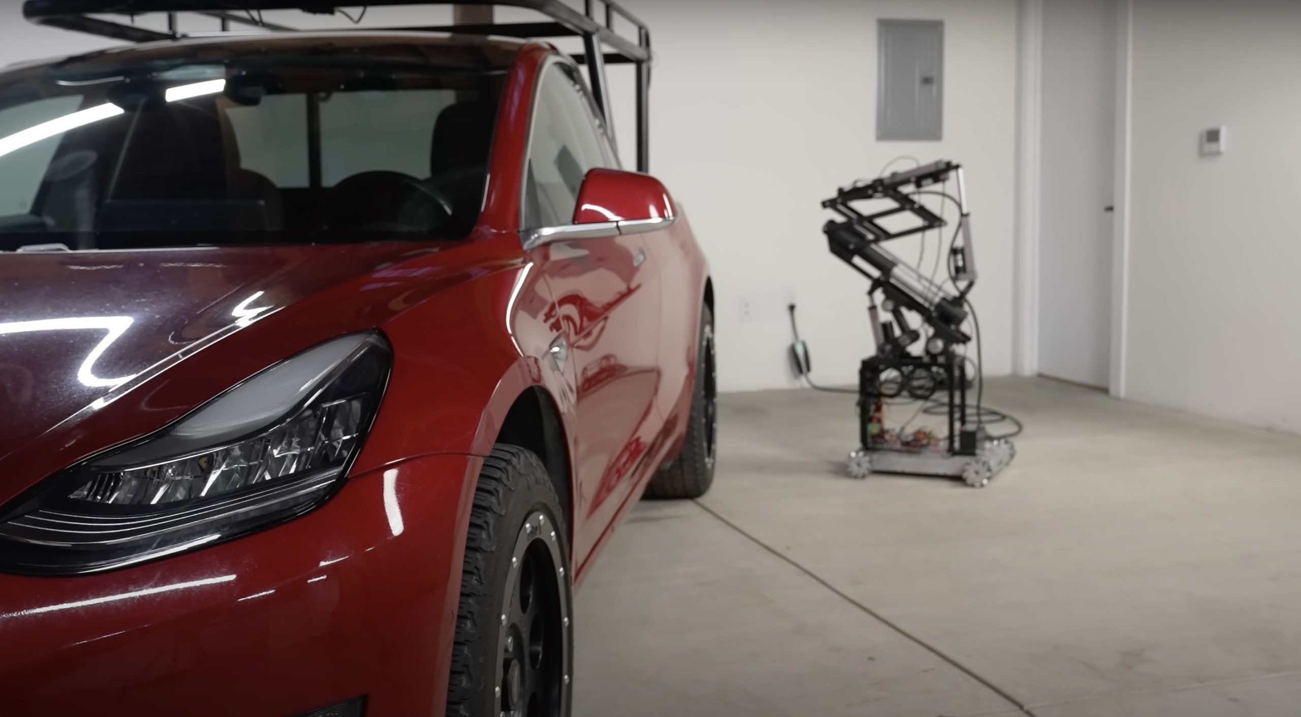
The “Queen of Sh*tty Robots” also opted to give Truckla a friend in the form of an automatic robot charger. Unlike Tesla’s rather interesting snake charger from years past, Truckla’s charger would come in the form of a rover, thanks to her friends at robotics platform Viam. Giertz aptly named Truckla’s robot charger friend “Chargela,” which is an appropriate name for such an invention.
Also true to form for Giertz, Chargela’s first encounter with Truckla was just a tiny bit awkward. One could say that Chargela may have just been a little bit nervous on his first try without human hands helping him. Most importantly, the system did work, so Giertz would likely keep using Chargela for her Model 3 pickup.
Teslas are very tech-heavy vehicles, so projects like Giertz’s Truckla are always remarkable. The fact that the Model 3 works perfectly fine despite having a good chunk of it cut off and turned into a pickup truck bed is mighty impressive any way one looks at it. Overall, Truckla will always be one of the coolest Tesla DIY projects to date, so any updates about the vehicle are always appreciated.
Truckla’s nearly four-year update can be viewed below.
Don’t hesitate to contact us with news tips. Just send a message to simon@teslarati.com to give us a heads up.
A Tesla owner is taking his hobby and love for electric vehicles to new levels by creating what could only be described as one of the coolest EV-related DIY projects to date. The idea for the project is simple: what happens when you cross a supercar with the Cybertruck? You end up with a two-seater CyberRoadster.
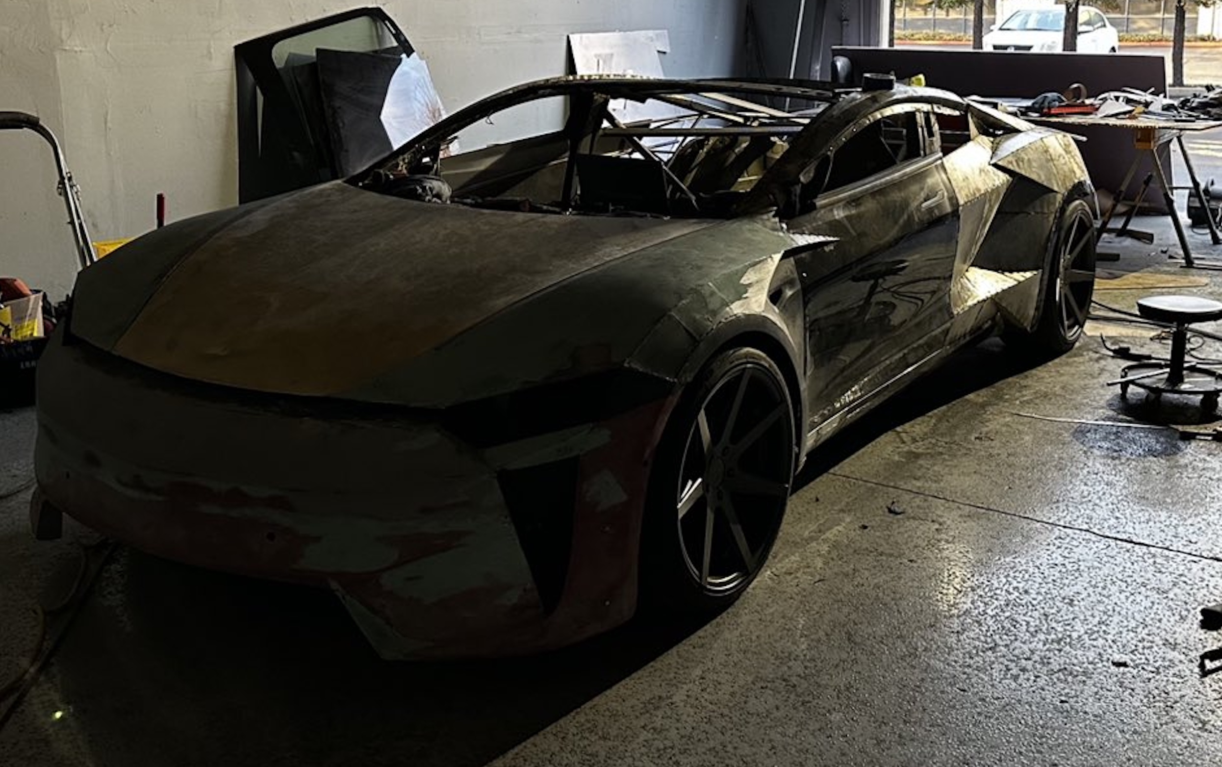
Tesla owner David Andreyev, who goes by the username @Cyber_Hooligan_ on Twitter, has spent the last few months creating a Cybertruck-inspired version of the next-generation Roadster made from a salvaged Model 3 Performance. Starting with a Model 3 Performance is an inspired choice, considering that it is Tesla’s first vehicle that has a dedicated Track Mode.
A look at Andreyev’s YouTube channel, which can be accessed here, shows the meticulous build that the Tesla owner has implemented on the project car. What’s particularly cool about the CyberRoadster is the fact that it’s being built with parts that are also from other Tesla vehicles, like its front bumper that came from a new Model S. Recent videos suggest that the project car’s rear bumper will be from a new Model S as well.
The journey is long for Andreyev, so the completion of the CyberRoadster will likely take some more time. Despite this, seeing the Tesla owner’s DIY journey on such an epic build is more than satisfying. And considering that the CyberRoadster is evidently a labor of love from the Tesla owner, the final results would likely be extremely worth it.
There’s a lot of crazy Tesla modifications that have been done as of late. But some, as it is with a lot of things on the internet these days, have become more silly gimmicks than serious automotive projects. Fortunately, car enthusiasts like Andreyev, who just happen to also love electric vehicles, are taking it upon themselves to create one-of-a-kind EVs that would surely capture the attention of anyone on the road.
Check out the latest video in the CyberRoadster’s creation below.
Don’t hesitate to contact us with news tips. Just send a message to simon@teslarati.com to give us a heads up.

Tesla finally clarifies fatal Texas crash, confirms driver manually overrode acceleration

SpaceX makes $20 billion move to optimize its balance sheet


